Video sub-formats
Background
As mentioned previously, there are currently defined two different video sub-formats. The video sub-formats are used to encapsulate coded (compressed) video data of different coding standards (codecs) such as JPEG, MPEG-4, H.264 or H.265 data. The video stream is handled (in GenericByteData form) by the system in two different ways, which corresponds directly to the two different video sub-formats:
- Video stream as individual coded pictures
- The stream is divided into packets where each packet corresponds to a coded picture in a form that is valid for the specific video codec type (for some video codecs and for a certain interlacing variant, a packet may actually contain two coded pictures forming a full interlaced frame as explained later). The packets may be dependent on each other (relative the actual video codec) as they together form the video stream.
- Video blocks (sequences of coded pictures)
- The video stream is divided into small sequences or blocks of coded pictures that together form a short independent video sequence that can be handled completely separate of any other video block.
The first sub-format is referred to by its appellation video stream packet and the other sub-format being referred to by video block. These two sub-formats and their differences are described in more details in the following sections.
Video stream synchronization points
In any handling of video streams by the system, there is a necessity for appropriate synchronization points. These points in the stream constitute a proper way of synchronizing the handling and processing (e.g. decoding) of the stream. The points are obviously coded pictures, and therefore these points are also referred to as synchronization pictures (or in shorter form SYNC picture/point). The re-synchronization of the processing at these points allow recovering from errors in the stream, e.g. losses of packets/pictures, or to get the processing properly started in the first place. The SYNC pictures are particularly important in MPEG-like codecs (e.g. MPEG-4 or H.263) having the inter-dependence between the coded pictures. For these video codecs, there are thus also points in the stream that are not SYNC pictures (e.g a P-picture in MPEG-4) and cannot, in general, be used for proper re-synchronization. A non-SYNC picture is defined to always be associated with one, and only one, SYNC picture. This associated SYNC picture always comes before the non-SYNC picture in time in coding order. Furthermore, it is required that a SYNC-point also marks a distinct "barrier" in the video stream meaning that no following picture may use any picture prior to the SYNC picture for reference. Note that some video codecs may define that all pictures are always SYNC points as is the case for e.g. the M-JPEG codec. Another term for a SYNC picture that is often used is the key-frame term; hence a key-frame means a SYNC picture.
A synchronization point marks a point in the stream from where decoding can start from scratch without any other information than the one given by the SYNC picture (and the sub-format header). Therefore for some video codecs, a SYNC point also contains some video stream information apart from the actual coded picture, where this information is an integral part of the video data and is thus defined by the video codec standard of the encapsulated video data. One example of such integrated stream information is the Sequence Parameter Sets and Picture Parameter Sets of the H.264 video codec as also explained later. Usually, this information is only provided for the SYNC picture and not for the non-SYNC pictures, and therefore the information is valid until the following SYNC point, but this is entirely determined and formalized by the video coding standard. Even though the stream information normally does not change within a stream, it must be repeated for each SYNC point to enable the re-synchronization to occur at any SYNC point.
This means that a video stream can be divided into smaller sequence parts consisting of one or more coded pictures. These coded pictures constituting a single sequence include exactly one SYNC picture (with the video stream information) and a number of non-SYNC pictures. The number of non-SYNC pictures may be zero. This division of the full stream will be referred to as a video sequence and is directly related to the common GOP (Group Of Pictures) term, although the more general video sequence term will be preferred. A video sequence is defined to be entirely self-contained and completely independent of other video sequences of the same stream (and of other streams). A long video stream therefore consists of many shorter video sequences. For several reasons, it is often preferred that the system handles relatively short video sequences (usually less than a few seconds long). The division into video sequences allows e.g. fast random access and also allows the system to throw away previous sequences relative a current sequence, because this current sequence would be independent of the previous sequences. As noted above, a SYNC point acts as a barrier in the stream, which translates to that a video sequence must be closed, i.e. a sequence is a closed GOP. No picture in the video sequence can refer to (e.g. be predicted from) any picture outside of the video sequence. If this is the case, the sequence is said to be open, which is not handled by the system. All video sequences are thus closed.
Any coded picture in a video stream for any codec is by the system categorized as either being a SYNC point or a non-SYNC point. This is marked by a flag in the sub-format header as explained later. Video stream packets are defined to contain a single coded picture relative to the encapsulated video codec. A video stream packet must not contain more or less of the video stream data (nor any other data) than what is required to represent the single picture according to the video coding standard. The exception to this is that for some codecs and in a certain interlacing variant (as detailed later), a video stream packet may contain what is formally two coded pictures that together form a single (interlaced) frame. The direct relationship between packets and coded pictures defines that each video stream packet will contain either a SYNC picture or a non-SYNC picture, and thus not both, except (and only) in the case of the special interlacing variant with two coded pictures in the same stream packet, where a SYNC-point packet will contain exactly one SYNC picture followed by one non-SYNC picture (and no other variations are allowed). A SYNC point as a video stream packet also contains the video stream information as required by the codec.
A video block, on the other hand, contains one or more pictures corresponding to exactly one (closed) video sequence, i.e. a video block is a video sequence. Such a block consists of at least one picture being the SYNC picture. A video block is thus defined to be equal to exactly one video sequence (GOP), and each block contains exactly one SYNC picture being the first coded picture of the block. Additionally, a video block may contain a number of non-SYNC pictures but is also allowed to not contain any, i.e. a block is allowed to be comprised of just a single SYNC picture as is the case for e.g. JPEG pictures. SYNC points are thus inherently connected to video blocks as each block must start with a valid SYNC point. A video block can be constructed from a sequence of video stream packets as shown in the figure below. The video block sub-format defines that the encapsulated video data is comprised of the coded video data from all the pictures (video stream packets) in the sequence concatenated together into a small separate "video stream". Note that the video block sub-format does not include the individual video stream packet sub-format headers but only defines its own sub-format header.
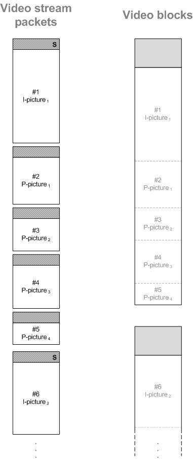
Illustrating the relationship between video stream packets and video blocks for an MPEG-like codec using the common I- and P-picture denotations with the SYNC points marked by the S in the stream packet headers. The video blocks have no similar marking because they are by definition always SYNC points.
Video stream packets
The video stream packet sub-format is generally used for live video data handling (e.g. when viewing live video in a client connected to a system). The sub-format represents the video stream divided at the granularity of individual coded pictures; thus each packet corresponds to one coded video picture (in general, because for certain video codecs and interlacing variant a packet may contain what is formally two coded pictures as mentioned before and detailed later). The actual encapsulated video data regardless of video codec is always in the native form of that codec, i.e. in the base bitstream representation of the video data, which is detailed later for each codec.
The video stream packet header
As given previously in the sub-format table, the data type value for a video stream packet is 0x0010. The rest of the video stream packet header and its layout is given in the figure below. The graphical layout in that figure (and other subsequent figures) has the different header fields separated in the horizontal direction (top to bottom) with the bytes used to represent the values of the fields given in the vertical direction (left to right) following big-endian byte ordering. This means that the first byte of the header is the one in the top-left corner (as part of the data type value) with the last byte of the header being the right-most one in the lower end (last row) of the illustration. In other words, the byte index (position) into the header increases going left to right and then downwards to the next row starting from the left again. The relative zero-based byte index into the header is shown to the left of the header fields, where the first byte of the header has index 0. As an example, the header field 'Sequence number' is located at byte index 8 of the header, and as the field is a 16-bit (two-byte) value the last byte of the field will be at index 9.
- Note:
- The header is assumed to be initialized with zeros (i.e. all bytes of the full header is filled with
0x00), which means that the default value for all fields at initialization and for any unused or reserved fields is the zero value. All normal fields obviously contain some value within a given allowed range, which some times does not allow the zero value as a valid value for that header field. This zero-initialization of the header goes in general for any GenericByteData sub-format.
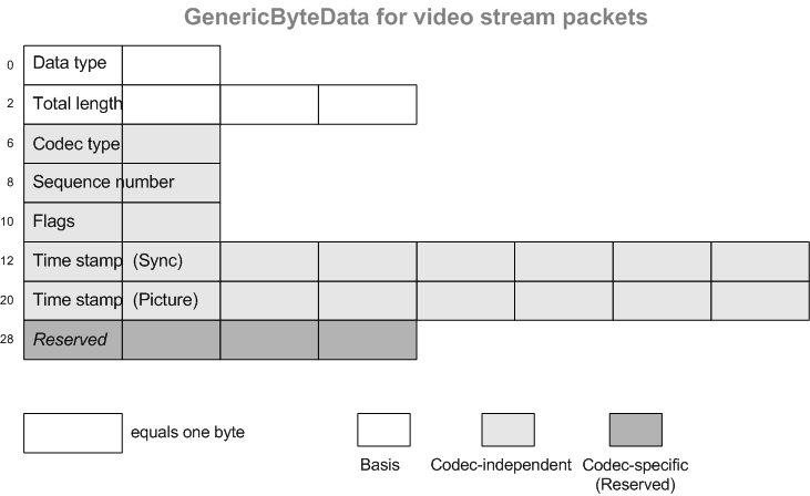
Illustration of the header for the video stream packet sub-format.
The different header fields, their interpretations and their values are described in the following with reference to the figure above. Please note the three sub-categories of header fields as indicated by the different shading of the fields, with the basis fields being the base information of the header (which are actually similar to the first header fields of some other sub-formats as well). The codec-independent header fields indicates that the information in those fields are not dependent on the video codec of the encapsulated video data, whereas the last header fields in dark shading are specific to the encapsulated video codec (but are also considered reserved as explained below). The header layout is fixed and so is the length of the header being 32 bytes long.
- 'Data type'
- The data type is fixed to a value of
0x0010for the video stream packet sub-format. No other value is used to indicate this sub-format. - 'Total length'
- This header field contains the total length in bytes of the entire video stream packet. The length includes the length of the full header (including this and the previous header field), so the actual length of encapsulated video data is found by subtracting 32 from the given value. This also means that the value in this field will be at least 32. The field is an unsigned 32-bit value, which means that no single packet can be longer than (2^32)-1 bytes. In practice, video stream packets will be much shorter than this allowed maximum.
- 'Codec type'
- This 16-bit unsigned value indicates the video codec type of the encapsulated data. It thus also determines the exact interpretation of the last reserved header bytes. The currently defined values for codec type is given in the table below. Additional details on the support for the different codecs is given in a subsequent section. The codec type is normally fixed for a given stream. If it should change, it is only allowed to do so at SYNC points.
- 'Sequence number'
- This unsigned 16-bit value indicates a sequential number for the given packet. The number increases by one with each packet in the sequence (stream). The sequence number wraps at
0xFFFFto restart at0x0000for the next packet. The start value of the sequence number as the stream begins is arbitrary, and although it may often be0x0000, one cannot rely on a specific start value. The sequence number can be used e.g. to check for losses of video stream packets. - 'Flags'
- This 16-bit wide header field contains a number of codec-independent bit-flags. Bit-flags are boolean values that can be either set (the bit is 1) or not set (bit is 0). These flags are detailed in the next section. This field contains a number of bit-flags and also a value that is actually a combination of two bits. Having this bit-based header field allows to communicate several properties in a compact form. One of the important flags in this field is the so-called SYNC-flag that indicates whether or not a given stream packet is a valid synchronization point of the stream. These synchronization markers can be used e.g. to get back on track if synchronization has somehow been lost.
- 'Time stamp (Sync)'
This header field is represented by a 64-bit (unsigned) value that indicates the absolute time stamp of the synchronization point, which is related to the current video stream packet (i.e. the current coded picture). The synchronization point for a given packet/picture indicates the relationship between the current packet and its synchronization point. This will thus be the nearest previous synchronization point that has been in the stream and thus the time stamp of the synchronization point, which is associated with the current packet. If the current packet itself is a synchronization point, the synchronization time stamp will be identical to the picture time stamp field (as explained below). This header field will also be referred to by its shorter form SYNC time stamp. It can, among other things, be used to help identifying packet losses in case the sequence number is not sufficient (e.g. has wrapped around). The actual value stored is the absolute UTC time given as the number of milliseconds since the Epoch. This time epoch is in the system defined to be January 1, 1970, 00:00:00 UTC, which is also equivalent to the epoch used by Unix/Linux/POSIX time.
- 'Time stamp (Picture)'
This header field is represented by a 64-bit (unsigned) value that indicates the absolute time stamp of the current stream packet. The time stamp is represented in the same way as the SYNC time stamp, i.e. as the number of milliseconds since the Unix time epoch in UTC. The time stamp represents the transportation or arrival time of the packet in coding order and not necessarily (more often than not) the display time of the actual picture contained in the packet, which thus may be different from this. This field is equal in value to the SYNC time stamp field if and only if the packet is also a SYNC packet as given by the SYNC-flag of the 'Flags' field. Otherwise (for non-SYNC packets), the picture time stamp is always larger (i.e. later) than its associated SYNC time stamp.
- 'Reserved'
These 32 bits of the header are reserved. The information contained within these bytes are considered to be dependent on the actual codec of the encapsulated data as given by the 'Codec type' header field. The interpretation of this header field is reserved for future use. The value of the header field must be equal to the default value of
0x00000000.
Video codec type |
Comments |
|
|---|---|---|
| - Reserved - | Unspecified. |
|
JPEG |
M-JPEG |
|
MPEG-1 |
MPEG-1 |
|
MPEG-2 |
MPEG-2 |
|
MPEG-4 |
Any MPEG-4 |
|
MPEG-4 SH |
MPEG-4 Short-Header mode |
|
MPEG-4 ASP |
MPEG-4 Advanced Simple Profile |
|
H.263 |
H.263 |
|
JPEG-2000 |
JPEG-2000 |
|
H.263++ |
H.263 with PLUS-types |
|
H.264 |
H.264 (MPEG-4 Pt. 10 / AVC) |
|
MPEG-4 SP |
MPEG-4 Simple Profile |
|
MS VC-1 |
Windows Media 9 (WM9) |
|
H.261 |
H.261 |
|
H.265 |
H.265 |
|
AV1 |
AOMedia Video 1 |
|
MxPEG |
Proprietary codec from MOBOTIX. |
The video stream packet flags
The currently defined bit flags of the 'Flags' header field of the video stream packet header are detailed in this section. The flags are shown in the related figure, which shows the 16 bits of the two bytes of the field where the first bit (least significant bit) in the field is at position 0 (being the least significant bit of the second byte of the field) and the last bit (most significant bit) is at position 15 (being the most significant bit of the first byte of the field because of big-endian ordering). Only the bits shown in white are currently defined; all other bits shown in gray shading are reserved for future use. All these reserved and undefined bits must all be set to 0. The bit flags can be divided into three categories: the SYNC flag, interlacing properties flags, and flags for describing the coded picture orientation. In the following, an overview is given of the different flags and values of the 'Flags' header field.
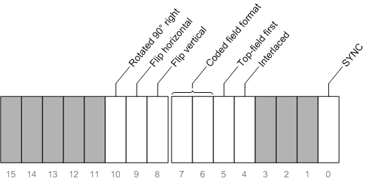
Illustration of the bit-flags defined for video stream packets in the 'Flags' field of the video stream packet header.
- SYNC (bit #0)
- This single-bit flag is used to mark if a given stream packet contains a synchronization point in the video stream or not. In case of a bit-value of 1, the SYNC flag is set, and this means that the packet is a synchronization point in the stream. When the flag is not set the packet does not contain a SYNC point. An example of a SYNC point (as also explained later) is an I-picture of an MPEG-4 stream, whereas P- and B-pictures are not SYNC points. All JPEG pictures of an M-JPEG stream are valid SYNC points, and therefore any video stream packet containing a JPEG picture will have the SYNC flag set.
- Interlaced (bit #4)
- This single-bit flag is one of four bits used to describe the interlacing properties of the current packet. This flag indicates whether the encapsulated coded video data is interlaced or not. A value of 0 means that the video is not interlaced (hence progressive), whereas a value of 1 means the video data is in an interlaced format. If and only if this flag is set to 1, the three remaining bits (being bits 5-7) for describing the interlacing properties have a valid interpretation; otherwise (if this bit-flag is not set) all the three remaining bits must be 0. The interlacing properties and these related flags are described in more detail later. A video sequence is either interlaced or progressive, which means that this flag must only change at SYNC points.
- Top-field first (bit #5)
- This single-bit flag is part of the interlacing properties for the current packet. It only has a valid interpretation if the Interlaced flag as described above is set. The flag indicates whether or not the top picture field (sometimes also called the upper field) comes before (first) in time of the bottom (lower) picture field. The top field refers to the picture field that contains the first line of the full frame (even-numbered lines 0,2,4,..), whereas the bottom field refers to the field with the odd-numbered lines (1,3,5,..). Being a top or a bottom field thus indicates the spatial relationship of the two fields within the full frame. Sometimes this is described by the two picture fields having different parity and that they together form a field pair. The fact that the top field is then first as indicated by this flag means that the top field represents the picture field that comes first in time (earliest). If the bottom field, on the other hand, is first that field is then first in time (earliest) with the top field following it. This flag thus describes the temporal relationship of the field pair (in display order). If the flag is not set, the bottom field is indicated as being first. The temporal relationship of the field pair of a stream must stay the same within a video sequence, i.e. changes to the value of this flag must only occur at SYNC points.
- Coded field format (bits #6 and #7)
- This is actually a two-bit value that is part of the interlacing properties for the current packet. It only has a valid interpretation if the Interlaced flag is set. The two bits provides four different values that describes the format in which the picture fields of the interlaced video stream has been coded. The coded field format mainly indicates the spatial organization of the coded picture fields in the video stream. If the Interlaced flag is not set, the two bits must both be set to 0. In general, the value of this field must be constant for a video sequence, i.e. it can only change at SYNC points, although there is an exception to this as explained later when detailing the available values for different picture field formats.
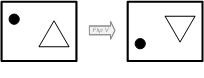
- Flip vertical (bit #8)
- This single-bit flag is one of three bits for describing the so-called coded picture orientation, which is explained in more detail in a subsequent section. The flag indicates whether or not the coded picture is coded with a geometric orientation that is flipped (mirrored) vertically relative the regular orientation (logical viewpoint). If the flag is set (equal to 1), the coded picture is flipped vertically, otherwise with the flag not set, the picture orientation is not flipped vertically. This flag including the two other coded picture orientation flags must stay the same for a video sequence and is thus only allowed to change at SYNC points.
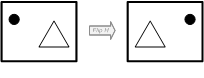
- Flip horizontal (bit #9)
- This single-bit flag is a part of the coded picture orientation properties for the current video stream packet. The flag indicates whether or not the coded picture is coded with a geometric orientation that is flipped (mirrored) horizontally relative the regular orientation (logical viewpoint). Only when the flag is set, the picture orientation is flipped horizontally. This flag must be constant for a video sequence and is thus only allowed to change at SYNC points.
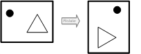
- Rotate 90 degrees right (bit #10)
- This single-bit flag is also a part of the coded picture orientation properties for the current video stream packet. The flag indicates whether or not the coded picture of the current packet has been coded with a rotation by 90° to the right (clock-wise) relative the regular logical orientation. If the flag is set, the orientation is rotated by 90° clock-wise, otherwise, if the flag is not set, there is no rotation of the picture orientation. Similar for the other two picture orientations flags, this flag must also only change its value at SYNC points.
Interlacing properties and the related flags
The interlacing properties through the flags in the video stream packet header provide information on the use of interlacing in the coded video data. In general, it is not possible to deduce this kind of information from any video stream. The video may be interlaced even though it has been coded as progressive, or the video is compressed with a codec that does not provide any formal facility for indicating interlacing. The interlacing properties are described via the four bits of the 'Flags' header field defining the three values; the Interlaced bit-flag, the Top-field first bit-flag and the Coded field format value. As mentioned previously, the interlacing properties are only in effect if the contained video data is actually interlaced as given by the Interlaced flag being set. The Top-field first flag indicates the temporal relationship of the coded fields, whereas the Coded field format value primarily indicates the spatial relationship of the fields. There are defined four different ways of representing this spatial relationship of interlaced content. These are illustrated in the figure and the table below.
In addition to the spatial relationship of the fields, the coded field format also indicates the way the interlaced content is represented by the video codec as coded pictures, i.e. whether or not a single coded picture contains both fields (as a full frame, in one of two ways) or if two individually coded pictures are used with one picture for each field (of each polarity) together forming the full frame as a field pair. The latter case is the only exception to the concept that a video stream packet contains a single coded picture, because for this (and only for this) coded field format, there will be two coded pictures in the same video stream packet describing the same frame. This is considered a special case and not a very common representation and it is also highly dependent on the video codec in use. Essentially, this case means that the video stream is field coded and can thus only be utilized for codecs that actually support the use of field coding. Currently, this is only supported for H.264. The rest of the coded field format variants are all considered as a form of what is commonly referred to as frame coding. The use of adaptive frame/field coding at the picture level is allowed. In this situation (and only in this situation), where some coded pictures may represent a full (interlaced) frame and other coded pictures may be coded as separate fields, the coded field format is allowed to change at each video stream packet even for non-SYNC points matching with how the data in the packet has actually been coded. This is the only situation where the coded field format is allowed to change for a video sequence; otherwise it must remain the same throughout the sequence and can thus only change at SYNC points. Adaptive frame/field coding is only allowed for video codecs that actually defines such coding behavior (currently only supported for H.264).
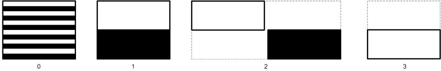
Illustrating the four defined coded field formats for interlacing where the black and white parts indicate the two field polarities (top and bottom).
- One picture with two fields, interleaved (0)
- The two fields are coded with their lines interleaved together into a single picture (frame). This is a fairly common way of coding interlaced content. This matches with the use of frame coding. In case of adaptive frame/field coding, this value is used to mark the packets containing frame-coded pictures.
- One picture with two fields, separate from each other (1)
- The two fields are coded into a single picture but the fields are separate from each other (non-interleaved) and are placed "on top of" each other in the full picture. This format will require special care in typical display scenarios, e.g. by interleaving the lines of the two fields together making it similar to the common format that has value 0 (above). This coded field format must remain the same for a video sequence and can thus only change at SYNC points.
- Two pictures with the two fields coded as individual pictures (2)
- The stream packet contains as an exception two coded pictures where each picture represent one of the two fields of the field pair. Both field polarities (top and bottom) are present in the packet. The fields when forming the full frame are considered as being interleaved, i.e. the ordinary decoded output (e.g. for display or combined with picture orientation) would be as a full frame similar to the common format that has value 0 (above). In case of adaptive frame/field coding, this value is then used to mark the packets that contain field-coded pictures. The use of this format is highly codec dependent. The picture time stamp associated with a video stream packet containing two field-coded pictures, which is the case for this format, is the time stamp belonging to the field (picture) that is first in coding order. There is no separate time stamp for the second picture of the packet. In other words, the time stamp belongs to the full frame consisting of both fields.
- One picture being a single field of one polarity only (3)
- This may be seen as a special case of an interlaced format where only one of the polarities (and never both) exists in the stream. It is thus not really an interlaced format but rather more a pseudo-progressive representation of the video at half the vertical (and temporal) resolution. Video appearing in this format may often originate from actual interlaced video where half of the fields have been thrown away before encoding (and thus not as part of any subsequent handling of the compressed stream, so this is not used in any way to indicate e.g. data losses with lost fields). Being a pseudo-progressive format, this format matches with use of ordinary frame coding. This coded field format must remain the same for a video sequence and can thus only change at SYNC points.
Coded field format | Graphical representation | |
|---|---|---|
| |  |
| |  |
| |  |
| |  |
Coded picture orientation and the related flags
There may be situations where the video captured by a camera or similar for various reasons needs to be in a different orientation when coded. The coded pictures of such video thus have an orientation that is different from the original captured orientation. The original captured orientation is the logical viewpoint of the video. The geometrical relationship between the coded picture and the logical viewpoint of the picture from a human visual perspective will be referred to as the coded picture orientation. The logical viewpoint is the normal preference for representing the 2-D picture mapping of a real-world scene as performed in a video camera when the video is captured. The viewpoint can be found by imagining that a human person replaces the video camera with the eyes being the lens and the orientation of the person adhering to that of the camera. The logical viewpoint will also be referred to as being the regular orientation (of the coded picture).
For normal coded video the picture is assumed to be rectangular in format, which is also the general assumption throughout the system and in many video coding standards as well. There are defined three basic geometrical operations for describing the coded picture orientation of rectangular video. These are vertical flipping, horizontal flipping, and rotation by 90 degrees clock-wise. The three operations are defined by the associated bit-flags in the 'Flags' header field as summarized in the table below. The flipping operation is also often referred to as mirroring. All combinations of flipping and rotation in steps of 90 degrees can be described by these three bit-flags, and all operations are relative the regular orientation. The order of the operations during encoding follows the order given in the table, i.e. vertical flipping is performed first followed by horizontal flipping and finally by rotation, if they are applicable. The reverse order starting with rotating back must be applied when converting a decoded picture to the regular orientation.
Coded picture orientation | Graphical representation | |
|---|---|---|
| |  |
| |  |
| |  |
Note that the coded picture orientation properties are only used to indicate the orientation of the coded pictures that are somehow coded different from the original captured orientation. It is thus not used for describing the orientation of the camera (e.g. ceiling-mounted) as that is normally taken care of by the camera itself (before encoding). The properties can be used to help handling such video data when it is decoded and displayed or similar. The picture orientation properties are constant for a video sequence and are thus only allowed to change at SYNC points, even though they are delivered for each video stream packet. So all non-SYNC packets associated with a given SYNC packet will have the same orientation properties as that SYNC packet.
The combination of interlaced video and coded picture orientations different from the regular orientation is unconventional and should be avoided. Interlaced video makes most sense if the orientation is regular. Nevertheless, any combinations of different picture orientations and interlacing are formally possible adhering to the rule that the interlacing properties apply to the regularly-oriented picture. This means that the order of processing in the coding stage is defined to consist of first interlacing followed by an optional change in picture orientation. At the decoding stage, the order must be reversed so that the picture orientation is handled first producing the regularly-oriented and interlaced picture. This follows the logical steps occurring in a typical video camera or similar device, where the video is captured in an interlaced format and then the pictures are, for some reason, coded in an orientation different from the regular orientation.
Video codec support
The actual video codec support is determined by the system in combination with the support defined for the GenericByteData format. The different video codecs given in the previous table overview of the codec type values are the ones currently supported. Open non-proprietary video coding standards are preferred with one exception being the proprietary MxPEG codec. Most of the comments in this section also apply to the codec support for video blocks with the main difference being the different way of specifying the codec type in that sub-format header (as explained later). Note that all video data is always delivered in the logical coding order as defined by the associated video standard; this is not necessarily (and is often not) equal to the display order of the pictures. In the following, the support for the different video codec types is detailed. The comments on which e.g. parts, profiles and coding tools that are supported for each codec are on purpose not detailed in this document as that is subject to change and relies on what the system may offer. Therefore, the comments given here mainly focus on general codec support and the handling of the coded data in relation to the GenericByteData format encapsulation. That handling should in general hold but may also change with expanded support for certain codec features. Generally, for all currently supported codecs the Pixel Aspect Ratio (PAR) of the coded video where applicable is handled. If the PAR is not given explicitly, a default aspect ratio value of 1.0 (1:1) is assumed.
M-JPEG
The video codec type indicated by a value of 0x0001 in the 'Codec type' header field defines that the encapsulated video data follows the JPEG image coding standard. This is often also referred to as M-JPEG (or Motion JPEG) but in reality it is just a series of individual JPEG pictures that works as a video sequence and thus being able to depict motion. It will be referred to as simply JPEG. The formal definition of the JPEG standard is given in ITU T.81 and equivalently in the ISO/IEC 10918-1 standard. The encapsulated JPEG data must be a complete JPEG picture with full headers and thus not in an abbreviated form. The aspect ratio information of the JPEG File Interchange Format (JFIF) header is handled by directly translating it into a normal pixel aspect ratio indication regardless of the way it has been indicated. If not explicitly present, the default 1.0 (1:1) aspect ratio is assumed. As a JPEG picture is always a valid SYNC picture, JPEG pictures may some times be handled by the system as single-picture video blocks rather than stream packets.
MPEG-4 Part 2
This covers the ISO video coding standard MPEG-4 Part 2 (formally ISO/IEC 14496-2). This is not the same as the MPEG-4 Part 10 standard (equal to H.264) and will in short form be referred to as simply MPEG-4. MPEG-4 Part 10 / AVC is covered by the H.264 video codec type. Currently, only the Simple Profile (SP) and the Advanced Simple Profile (ASP) of the natural video coding profiles are supported, which also includes support for the so-called Short-Header mode, which is compatible with baseline H.263. Only a single visual object at a single video object layer is supported (i.e. multiple objects and/or layers are not supported). The MPEG-4 codec is covered by several codec type values as given in the table, i.e. the values 0x0004, 0x0005, 0x0006, and 0x000B. The general codec type is the one defined with value 0x0004 covering all supported MPEG-4 data. The three other values cover different sub-sets of the standard (Short-Header mode, Advanced Simple Profile, and Simple Profile, respectively). The general type value indicating "general MPEG-4" (to the extent of what is supported) should be used even if one of the specialized values may be applicable. Nevertheless, the system may deliver data that indicates either of these types, and normally they should all be handled the same way. A SYNC-picture for MPEG-4 video data is defined to be an I-picture with the relevant stream configuration data prefixed. The encapsulated data for a SYNC-picture is thus the combination of so-called configuration data (video stream information) and the elementary stream data for the single visual object and its single layer and its video object planes.
H.263
This covers the entire ITU video coding standard H.263 including the various "PLUS versions" combined with the Annexes of the standard, although not all may be supported by the system. Two codec type values are defined with 0x0007 being the general one covering any (supported) part of the standard. The codec type value 0x0009 indicates specifically that the video data is a "PLUS type" H.263 (H.263++). Similar to what has been noted for MPEG-4, the "general H.263" value should be used even if the encapsulated data follows H.263++, although the system may deliver data with the other type being indicated but should generally be handled in a similar way. A SYNC-point is defined to be an H.263 I-picture with the full PLUS-type header included (if applicable). The encapsulated data follows the bitstream syntax defined by the standard. Each stream packet encapsulates a single coded picture
H.264
This covers the ITU video coding standard H.264 that is also equivalent to the ISO standard MPEG-4 Part 10 / AVC (formally ISO/IEC 14496-10). To avoid confusion with MPEG-4 Part 2, this standard will only be referred to by the H.264 name, and therefore any reference to just "MPEG-4" refers to MPEG-4 Part 2 and thus not to H.264. Currently, the support for H.264 is broad in scope covering the following profiles (with a number of restrictions) supported at all defined levels: Baseline, Main, Extended, and High. Any H.264 stream is given by the codec type value 0x000A. In H.264, the SYNC-point is defined to be an IDR-picture, which is also an I-picture. A stream packet encapsulates one coded picture, which according to the standard is equal to an Access Unit (AU). All NAL units for a given AU are provided within the same stream packet and as a result of this, a stream packet always contains at least one NAL unit and always contains complete NAL units. The only exception to this is in the special case of field coding, where each video stream packet contains both fields of a field-pair, which means that the packet in that situation contains two AUs. This is marked by the appropriate interlacing property as previously described. In this situation, a SYNC packet will thus contain both a SYNC picture (the IDR picture) followed by a non-SYNC picture. An ordinary (non-IDR) I-picture is not sufficient for the SYNC-point requirements, so although they may be seen as a sort of a "key-frame", normal I-pictures are not considered SYNC-points and is thus allowed to occur within a video sequence as non-SYNC points. All non-SYNC pictures will be non-IDR pictures in line with the standard. The format of the encapsulated data follows the byte stream format defined in Annex B of the H.264 standard with proper start codes added before the NAL units. For each IDR picture being a SYNC-point, the associated Sequence Parameter Set (SPS) and Picture Parameter Set (PPS) NAL units must be included.
H.265
This covers the ITU video coding standard H.265 (also known as HEVC). Currently, the support for H.265 is broad in scope covering all profiles supported at all defined levels. Any H.265 stream is given by the codec type value 0x000E. In H.265, the SYNC-point is defined to be an IDR-picture, which is also an I-picture. A stream packet encapsulates one coded picture, which according to the standard is equal to an Access Unit (AU). All NAL units for a given AU are provided within the same stream packet and as a result of this, a stream packet always contains at least one NAL unit and always contains complete NAL units. The format of the encapsulated data follows the byte stream format defined in Annex B of the H.265 standard with proper start codes added before the NAL units. For each SYNC-point, the associated Video Parameter Set (VPS), Sequence Parameter Set (SPS) and Picture Parameter Set (PPS) NAL units must be included.
AV1
This covers the Alliance for Open Media (AOMedia) video coding standard AV1 (also known as AOMedia Video 1). Currently, the support for AV1 is broad in scope covering all profiles supported at all defined levels. Any AV1 stream is given by the codec type value 0x000F. In AV1, the SYNC-point is defined to be an IDR-picture, which is also an I-picture. A stream packet encapsulates one Temporal Unit (TU), which can contain multiple coded pictures, but only one that is marked for display. All Open Bitstream Units (OBU) for a given Temporal Unit are provided within the same stream packet and as a result of this, a stream packet always contains at least one OBU and always complete OBUs. The format of the encapsulated data follows the low-overhead bitstream format defined in Section 5.2 of the AV1 standard. For each SYNC-point, the Temporal Unit must include the associated Sequence Header OBU.
MxPEG
The MxPEG codec is a proprietary standard developed by the German company MOBOTIX based on the JPEG standard. This involves two types of pictures, where one is a full JPEG picture conforming to the standard but with some additional MxPEG-specific user data embedded (still within the standard). The other picture type is a sort of a "delta picture" that contains only those macroblocks that have been determined as changed since the previous picture and is therefore delivered in a specialized (non-compliant) JPEG format containing just those blocks. The first picture type, which is essentially equal to a JPEG picture is defined by the system to be a SYNC-point. The stream packet format contains one MxPEG picture per packet. The codec type value defined for MxPEG codec is 0x0080
Video blocks
As previously described, the video block sub-format mainly differs from the video stream packet sub-format in that the block encapsulates a short sequence of coded pictures whereas the stream packet only encapsulates a single coded picture and is thus a further subdivision of the stream. In general, video blocks are used for handling recorded video data, but may also be used for live video in some situations. The sub-format is described in more detail in the following.
The video block header
The video block sub-format is identified in the GenericByteData header by the data type value being within the range of 0x0001 to 0x000F. This is different from the video stream packet sub-format that is identified by just a single data type value (0x0010). The data type for a video block also contains information on the video codec of the encapsulated data as detailed below. The rest of the video block header and its layout is given in the related figure below. The graphical layout of that figure is similar to that of the figure for the video stream packet header.
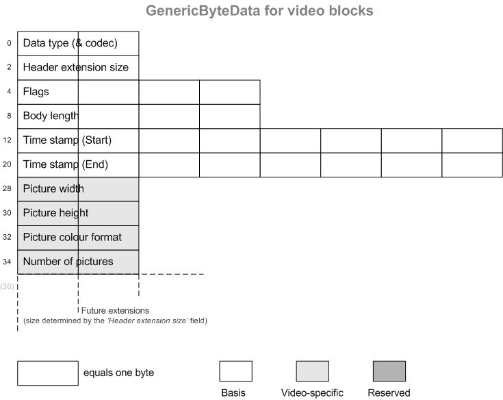
Illustration of the header for the video block sub-format.
The different header fields of the video block header are described in the following with reference to the figure above. The base header layout is fixed, and this has a length of 36 bytes. The header can be extended for future use by indicating an extension length in the 'Header extension size' field. However, this functionality is currently reserved, and therefore only non-extended video block headers exist.
- 'Data type (& codec)'
- The data type for a video block is in the range of
0x0001to0x000Fand serves the double purpose of also defining the type of video codec type of the encapsulated video data. The actual translation from data type values to codec types is given in the table below. - 'Header extension size'
- This header field indicates the number of bytes by which the base video block header has been extended. The field is a 16-bit unsigned value and thus allows header extensions up to (2^16)-1 bytes. As noted above, this is currently a reserved field, and no extended video block headers exist. Therefore, the value of this field should be
0x0000. - 'Flags'
- This 32-bit wide header field contains a number of codec-independent bit-flags. Most of the currently defined flags for the video block sub-format are identical to those defined for video stream packets, but this is explained in detail in a subsequent section.
- 'Body length'
- This header field represents as a 32-bit unsigned valued the length of the body of the video block, i.e. the length of the video data that comes right after the full video block header. This is thus equal to the total length of the video block chunk (header and body) subtracted the length of the (possibly extended) header. The length of the header is at least 36 bytes. The body length can not exceed a value of (2^32)-1 bytes subtracted the length of the header (so that the full length of the byte data chunk including the header does not exceed (2^32)-1 bytes). In practice, the length of a GenericByteData chunk representing a video block will be less than this allowed maximum.
- 'Time stamp (Start)'
- This field is represented by a 64-bit (unsigned) value that indicates the absolute time stamp of the start of the video block. The time stamp value is in the same format as that of the time stamps for video stream packets, i.e. the absolute number of milliseconds since the Unix time epoch in UTC. The start time stamp is the time stamp of the first picture of the block. A start time stamp of a current video block in a series of video blocks representing parts of the same video stream can not be equal to the start time stamp of the previous video block.
- 'Time stamp (End)'
This field is represented by a 64-bit (unsigned) value that indicates the absolute time stamp of the end of the video block. It is stored in the same format as the start time stamp described above. The end time stamp is the absolute time stamp of the last picture in the video block. Depending on the bit flag End time incl. last picture, the end time stamp is either at the time of the last picture (the flag is set), or the end time stamp includes the additional time span of the last picture (flag not set), i.e. the time between the last picture of the block and the first picture of next block (being the immediately subsequent block in time order). In the latter case, the end time stamp is not really a part of the video block (i.e. it points to the time at which the block has ended and not when it ends), and therefore it is allowed that the start time stamp of the subsequent video block (in time order) is equal to the end time stamp for the current block. The end time stamp and start time stamp is allowed to be equal to each other (for the same video block) if and only if the block contains a single picture; otherwise they cannot be equal. In case the start and end time stamps are indeed equal for a single-picture video block, the start (and end) time stamp of the subsequent block must not be equal to the start (and end) time stamp of the current block regardless of how many pictures are contained in that next video block.
- 'Picture width'
- This 16-bit unsigned value contains video stream specific information being the width in pixels of the coded pictures contained in the video block. See comments later on the picture size information matching the actual coded picture size.
- 'Picture height'
- This 16-bit unsigned value contains video stream specific information being the height in pixels of the coded pictures contained in the video block.
- 'Picture color format'
This 16-bit unsigned value contains video stream specific information being so-called color format of the stream. Currently, this value can only be and is thus fixed to
0x0003.- 'Number of pictures'
- This 16-bit unsigned value contains video stream specific information being the number of coded pictures contained in the video block. This may have a value of 1, if the video block only contains a single picture, which will be the case for JPEG pictures. A value of 0 is not valid. In case of interlaced coding of the video sequence, this value represents the number of full frames that are present in the video sequence, even in the special case of field-coded material, where some (or all) of the coded pictures are individual fields, and where this value may differ from the actual formal number of coded pictures present in the coded video sequence.
Corresponding codec type | |
|---|---|
| JPEG |
| - Reserved - |
| - Reserved - |
| MPEG-4 |
| MPEG-4 SH |
| MPEG-4 ASP |
| H.263 |
| - Reserved - |
| H.263++ |
| H.264 |
| - Reserved - |
| - Reserved - |
| H.265 |
| AV1 |
| MxPEG |
The video block flags
The video block header defines the 32-bit header field 'Flags' as described previously. The bit flags of this header field are detailed in the following section. The flags and their bit position within the header field are illustrated in the related figure. Only the bits shown in white are currently defined. The other bits shown in shading are reserved. There is one bit flag, which has been deprecated and is thus now reserved (hence its different shading). All the reserved and undefined bits must all be set to 0. Most of the bit flags are similar to those defined for the video stream packet sub-format. These include the flags for the stream interlacing properties and the flags for describing the coded picture orientation. These flags have generally the same meanings as the ones defined previously for video stream packets. The following overview of the flags will thus only focus on the small differences in the interpretation of these flags. Notice that the relative bit positions of these common flags are the same as the ones defined for video stream packets.
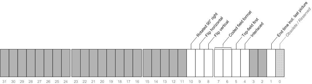
Illustration of the bit-flags defined for the 'Flags' field of the video block header.
- Obsolete / Reserved (bit #0)
This single-bit flag has been obsoleted and now has a reserved interpretation. Its value should be 0.
- End time incl. last picture (bit #1)
- This single-bit flag indicates whether the end time stamp of the video block is including the time stamp of the last picture or not. If the flag is set (value 1) the end time stamp does not include the time span of the last picture. If the flag is not set (0), the time span of the last picture is included in the end time stamp. See also the comments given for the end time stamp.
- Interlaced (bit #4)
- As for video stream packets, this flag indicates whether the encapsulated coded video data is interlaced or not. This flag is valid for the entire video block meaning that all pictures in the video block are either interlaced (flag set) or not. Only if the flag is set, is the interpretation of the remaining three interlacing bit-flags valid. If not set, all three bits must be 0.
- Top-field first (bit #5)
- As for video stream packets, this single-bit flag indicates the temporal organization of the fields of interlaced video. It only has a valid interpretation if the above Interlaced flag is set; otherwise it must be 0.
- Coded field format (bits #6 and #7)
- This two-bit value only has a valid interpretation if the Interlaced flag is set. The bits describe the same four different spatial ways in which the picture fields of the video block can be coded as those defined for video stream packets. The interlaced coded field format will be the same for all pictures contained in the video block. For the special case of adaptive frame/field coding, where the coded field format value for stream packets is allowed to change on a packet basis depending on whether a given packet is frame-coded or field-coded, it cannot be fully described by just this single value in the video block header. The convention is then that if the value 2 is used, it indicates that the video block contains some coded pictures (at least one pair) that are individually field-coded but some pictures in the block may be frame-coded (corresponding to the stream packet value 0). If the entire video sequence is field-coded (non-adaptive), the same value (2) must be used, whereas if the entire video sequence is frame-coded (i.e. no field-coding used) the ordinary value of 0 must be used.
- Flip vertical (bit #8)
- This single-bit flag is similar to the one defined for video stream packets and is thus also a part of the coded picture orientation properties for the video block. These coded picture orientation properties will be the same for all pictures contained in the video block. This flag indicates whether or not the coded pictures have been coded with a vertically flipped orientation.
- Flip horizontal (bit #9)
- This single-bit flag is similar to the one defined for video stream packets. The flag therefore indicates whether or not all the coded pictures of the video block have been coded with a horizontally flipped orientation.
- Rotate 90 degrees right (bit #10)
- This single-bit flag is similar to the one defined for video stream packets. The flag therefore indicates whether or not all the coded pictures of the video block have been coded in a rotated by 90° to the right (clock-wise) orientation.
The picture size information found in the video block header describes the actual coded picture size in the coded orientation format, i.e. the size and orientation of each coded picture as it is given in the compressed video data at the full frame height. Therefore, the picture size information will be equal to that for the full frame for any of the interlaced coded field formats even in the special case of field coding and also for method 3 of the coded field format, where the picture is considered as a full frame. For a rotated coded picture orientation, the picture size information will reflect that - for example, if a regularly oriented picture size is 320 × 240 (width × height), and it is coded in a rotated by 90° orientation, the actual coded picture size will be 240 × 320, and this will then be the size information stored in the video block header. Any pixel aspect ratio information present in the stream does not influence the coded picture size information given in the video block header, and therefore the ordinary output (display) resolution may be different from this coded resolution stored in the video block header.