Audio sub-formats
Background
There is only one sub-format for encapsulating audio data namely the sub-format for audio stream packets. This audio sub-format is described in the following sections.
One of the distinct differences between audio and video data is the fact that audio signals are one-dimensional signals as opposed to the two-dimensionality of video signals. In addition, the temporal sampling rate is much higher for audio compared to that for video. For audio data this corresponds to the sampling frequency (often equal to or larger than 8000 Hz), whereas for video it corresponds to the picture rate (often less than or equal to 60 Hz). The individual samples for audio data requires only little information (even in uncompressed form) as opposed to the data required to represent a single video picture. Due to the size of audio data, it is also tractable to convey the data in its uncompressed form (PCM). Furthermore, audio data may also involve one or more channels of audio data each containing a distinct audio signal. Therefore, audio data is normally conveyed as frames of audio samples for the different audio channels, i.e. a frame of audio data contains the short audio signals (audio samples in succession) of the individual channels.
Audio stream packets
The audio stream packet sub-format defines an encapsulation of audio data much in the same way as defined for the video stream packet with a few differences due to the difference in media type; one being that an audio stream packet represents an audio frame with potentially more than one channel of audio data. All audio frames are currently defined to be individual of each other, and they can therefore be compared to the SYNC points defined for the video stream packets. The sub-format header is shown in the figure below. The header layout is fixed, and its length is fixed to 42 bytes. The interpretation of the different header fields is given in the following.
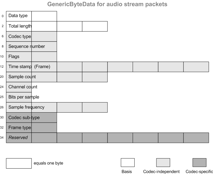
Illustration of the sub-format header for audio stream packets.
- 'Data type'
- The data type is fixed to a value of
0x0020for the audio stream packet sub-format. No other value is used to indicate this sub-format. - 'Total length'
- This header field contains the total length in bytes of the entire audio stream packet. The length includes the length of the full header (including this and the previous header field), so the actual length of encapsulated audio data is found by subtracting the header length (42) from the given value. This also means that the value in this field will be at least 42. The field is an unsigned 32-bit value, which means that no single audio packet can be longer than (2^32)-1 bytes.
- 'Codec type'
- This 16-bit unsigned value indicates the audio codec type of the encapsulated data. It thus also determines the exact interpretation of the last reserved header bytes. The currently defined values for codec type is given in the table below.
- 'Sequence number'
- This unsigned 16-bit value indicates a sequential number for the given packet. The number increases by one with each packet in the sequence (stream). The sequence number wraps at
0xFFFFto restart at0x0000for the next packet. The start value of the sequence number as the stream begins is arbitrary , and although it may often be0x0000that cannot be relied on. The sequence number can be used e.g. to check for losses of audio stream packets. - 'Flags'
- This 16-bit wide header field contains a number of codec-independent bit-flags. The bit-flags are currently reserved for future use, as no flags have been defined yet.
- 'Time stamp (Frame)'
- This header field is represented by an unsigned 64-bit value that indicates the absolute time stamp of the audio frame. Similar to what is defined for the video sub-formats, the stored time stamp value is given as the absolute number of milliseconds since the Unix time epoch in UTC. The time stamp is the absolute time of the first audio sample of the audio packet. As the precision of the indicated time stamp is in milliseconds, the time stamp may not be sufficiently precise to indicate the start time stamp exactly depending on the audio frame length and the sampling frequency. In practice, this should have no influence on the handling of audio stream packets.
- 'Sample count'
- This header field is an unsigned 32-bit value that represents the number of audio samples per channel in the audio data (frame). The sample count is the number of uncompressed (decoded) samples so this number does not represent the number of compressed samples for the codecs where such an interpretation is applicable (although often the number of compressed and the number of uncompressed samples will be equal).
- 'Channel count'
- This header field is represented by a single byte and indicates as an unsigned value the number of audio channels that are in the given packet data. The maximum number of channels is limited to 255, and the number must not be zero. In practice, only a few channels is supported by the system.
- 'Bits per sample'
- This header field contains as a single unsigned byte the number of bits per sample (per channel). The value represents the number of bits in an uncompressed and decoded sample, and thus does not provide the number of bits used to represent the coded/compressed data (which may be a variable number of bits per sample). Although the allowed range is from 1 to the maximum of 255, the set of typical values is very limited, e.g. 8 or 16. A value of zero is not allowed.
- 'Sample frequency'
- This header field is represented by 32 bits as an unsigned number providing information on the sample frequency of the each channel of the (uncompressed) audio data of audio packet. The sample frequency is given in Hz so that for example a sample frequency of 8 kHz is stored as a value of 8000. A value of zero is not allowed. Although the range of possible values is large, the typical subset of frequencies actually used is small.
- 'Codec sub-type'
- This header field is codec-dependent, i.e. its interpretation depends on the actual codec type given in the 'Codec type' header field. It is used to provide information on different sub-types of the codec. This is detailed later for each supported codec. If not used by a given codec, the value must be equal to the default value being
0x0000. - 'Frame type'
- This header field is codec-dependent, i.e. its interpretation depends on the actual codec type given in the 'Codec type' header field. It is currently not used by any codec, and its interpretation is thus considered reserved for future use. It must be equal to the default value
0x0000. - 'Reserved'
- The last 8 bytes of the header are reserved. The information contained within these bytes are considered to be dependent on the actual codec of the encapsulated data as given by the 'Codec type' header field. The interpretation of this header field is reserved for future use. All 8 bytes of the header field must be zeroed, i.e. equal to
0x00.
Video codec type | Comments | |
|---|---|---|
| - Reserved - | Unspecified. |
| PCM | Uncompressed raw PCM |
| PCM law | PCM companded with either A-law or µ-law |
| G.711 | Either A-law or µ-law |
| G.721 | 32 kbps |
| - Reserved - |
|
| - Reserved - |
|
| G.723 | 24 kbps or 40 kbps |
| - Reserved - |
|
| G.726 | 16, 24, 32, or 40 kbps |
| - Reserved - |
|
| AAC ADTS MPEG2 |
|
| AAC ADTS MPEG4 |
|
| - Reserved - |
|
Audio codec support
Similar to the video codec support, the actual audio codec support is determined by the system in combination with the support defined for the GenericByteData format. The currently supported audio codecs are the ones given in the table overview of the codec type values.
Uncompressed PCM
The audio codec type indicated by a value of 0x0001 in the 'Codec type' header field of the audio packet header defines that the encapsulated data is in the form of "raw" uncompressed PCM This is a very common way of representing digital audio with PCM being an abbreviation of pulse code modulation. Even though it is uncompressed, it is still defined and referred to as a "codec" here. For typical digital audio, as opposed to digital video, the amount of data required to represent it in a raw uncompressed form is reasonable and tractable. The encapsulated PCM data is allowed to be using essentially any sampling frequency and at any number of channels within the defined limits. In practice, however, only a limited subset of sampling frequencies and number of channels will be used. Currently, only 8 bits and 16 bits per sample are supported. These properties of the PCM data are all set in the respective header fields.
The individual sample values are stored in little-endian byte order. The samples for the different channels are interleaved together. This means that the first sample of the encapsulated data is the first sample of the first channel, and the subsequent sample will be the first sample of the second channel, and so on. In other words, the samples for all channels are grouped together on a sample-by-sample basis. This is exemplified below for two-channel 16-bit audio data. Samples for channel 1 are identified by the letter A, and samples for the second channel are identified by B. The least significant (low order) byte of a two-byte sample value is numbered with 0, and the most significant byte is given by 1; e.g. the byte B0 is the least significant byte of a sample for the second audio channel.
  Sample1 |Sample2 |Sample3 |
  A0A1B0B1|A0A1B0B1|A0A1B0B1| ...
This way of storing the PCM audio data follows that defined for the WAVE file format. No codec sub-types have been defined for this codec and thus the 'Codec sub-type' header field must be equal to 0x0000 as mentioned previously.
G.711
This defines audio data that is compressed according to the G.711 ITU-T Recommendation. It is given by a value of 0x0003 as its codec type. G.711 is fixed to a 8 kHz sampling rate and a single channel (mono) of audio. It thus cannot use arbitrary sampling rates or more than one channel; for that, the PCM companded codec can be used instead. G.711 compresses samples through logarithmic companding (compressing and expanding) of PCM samples. It is thus using a non-uniform quantization of the samples. Although the input samples are defined as 14-bit (or 13-bit), the codec is here defined as being 16-bit only when uncompressed. This means that the 'Bits per sample' header field must be equal to 16. If required, this can easily be achieved with proper shifting of the uncompressed samples (e.g. after decoding and converting to a 16-bit representation). Two different types of companding "laws" are allowed; either A-law or µ-law. Two associated codec sub-type values are defined for describing the type of companding used in the G.711 coding. A sub-type value of 0x0001 corresponds to µ-law companding, and a value of 0x0002 defines A-law companding. Any other sub-type value including 0x0000 is not allowed.
PCM with companding
This codec type defines conventional PCM companded with either A-law or µ-law as specified in the G.711 recommendation. The main difference between this and the G.711 codec is that this allows arbitrary sampling rates and multiple channels. The number of bits per sample is similar to G.711 fixed to 16 (uncompressed) resulting in 8-bit compressed code words. The code words for each channel are interleaved together similar to conventional uncompressed PC; e.g. for a two-channel (stereo) stream, the first byte will correspond to the code word for the first sample for the first channel; the second byte is the first sample for the second channel, and the third byte is the second sample for the first channel, etc. The value 0x0002 used in the 'Codec type' header field identifies the companded PCM format. Similar to G.711, there are defined two associated codec sub-type values defining the type of companding. A sub-type value of 0x0001 corresponds to µ-law companding, whereas a value of 0x0002 defines A-law companding. A sub-type value of 0x0000 (or anything else) is not allowed.
G.721
The G.721 ITU-T Recommendation for encoding of audio data sampled at 8 kHz to a 32 kbps representation through the use of adaptive differential pulse code modulation (ADPCM). Each sample is in compressed form represented by a fixed number of bits being 4 bits. The codec type value identifying G.721 is 0x0004. The G.721 recommendation has been superseded and incorporated into G.726. It is thus suggested to use G.726 for new devices or applications. The sampling rate is fixed to 8 kHz, and the number of bits per uncompressed sample is fixed to 16. It is also fixed that only one channel of audio can be handled. There are defined two valid codec sub-types that are used to distinguish between two different ways of conveying the 4-bit code words for the samples packed into the data bytes; either as "little-endian" or as "big-endian" ordering of the samples into the respective nibbles of the bytes. The little-endian ordering indicates that the code word for the first sample is located in the lower part of the first byte (octet) of the data containing the least significant bits of the byte, and the code word for the next sample is located in the upper nibble. For big-endian ordering, it is the exact opposite with the first code word placed in the upper nibble of the first byte containing the most significant bits of the byte. A sub-type value of 0x0001 indicates little-endian ordering whereas a value of 0x8001 indicates big-endian ordering. The most-significant bit of the sub-type value can thus be used as a flag for indicating, which type of endian packing of the code words that is used. This is equal to the behavior defined for G.723 and G.726 as explained below. All other values for the sub-type are reserved. The number of samples encapsulated must be an even number to ensure that the last byte of the coded data is fully packed (i.e. contains two code words). The number of samples, however, is suggested to be a multiple of 8 in order to have an integral number of milliseconds in one audio stream packet and to be consistent with the requirements for G.726.
G.723
The audio codec type value 0x0007 defines the G.723 codec as defined by the similarly named ITU-T Recommendation. The G.723 recommendation is merely an extension of G.721 for 24 kbps and 40 kbps. G.723 thus defines ways to encode monaural 8-kHz sampled audio with the use of ADPCM fixed-length code words of either 3 bits or 5 bits, respectively. As for G.721, the number of bits per uncompressed sample is fixed to 16. The G.723 recommendation has also been superseded by and is incorporated into G.726 and is therefore not recommended for new devices or applications. It is instead advised to use G.726. Similar to G.721 and as explained further for G.726, there are defined two ways of packing the code word samples into the data bytes using either "little-endian" or "big-endian" ordering. There are defined four different codec sub-type values indicating either 24 kbps or 40 kbps in combination with either little- or big-endian ordering. As for the G.726 and G.721 codecs, the most-significant bit indicates as a bit-flag whether or not big-endian ordering is used. A codec sub-type value of 0x0001 indicates 24 kbps, little-endian; a value of 0x0002 indicates 40 kbps, little-endian; and the values 0x8001 and 0x8002 are the respective big-endian counterparts. All other values are reserved. All data bytes must be fully packed and only contain complete code words. This means that for 24 kbps encoding with 3-bit code words, the data length in bytes must be dividable by 3, and for 40 kbps with the use of 5-bit code words the length in bytes must be dividable by 5. This corresponds to that the number of encoded samples in the encapsulated data must be a multiple of 8. Since the sampling rate is fixed to 8 kHz, this is equal to that the data contained must describe an integral number of milliseconds of audio as 8 samples equal one millisecond of audio. The minimum number of samples that must be contained in an audio stream packet for G.723 is thus 8.
G.726
The G.726 ITU-T Recommendation has superseded (and thus obsoleted) both G.721 and G.723. The G.726 recommendation thus encompasses both G.721 and G.723 defining ADPCM coding of audio data (monaural and sampled at 8 kHz) for 24 kbps, 32 kbps, 40 kbps, and also adds an option to code at 16 kbps using 2-bit fixed-length code words. It is advised to use this G.726 codec indication even if the bitrate matches one that is also defined by the obsolete recommendations. Similar comments apply to G.726 as given for G.721 and G.723, i.e. a single-channel stream sampled at 8 kHz with 16-bit uncompressed samples, and the number of samples encoded must be multiple of 8 to ensure completely packed data bytes with no partial code words. These requirements apply equally for any of the four encoding bitrates. The codec type value identifying G.726 is 0x0009. G.726 defines the use of the afore-mentioned two different ways of packing the code word samples into the data bytes; either "little-endian" or "big-endian" ordering of the code words. This is described in more detail in the following sub-section. There are defined eight different codec sub-type values. The codec sub-type value 0x0001 indicates 16 kbps encoding, little-endian; 0x0002 indicates 24 kbps, little-endian coding; 0x0003 indicates 32 kbps, little-endian; and 0x0004 indicates 40 kbps, little-endian coding. The respective big-endian counterparts are indicated by the bit-flag of the most-significant bit of the sub-type value, i.e. the values 0x8001, 0x8002, 0x8003, and 0x8004. All other codec sub-type values are reserved.
Little- and big-endian ordering of G.726 code words
For G.726 (and indirectly for G.721 and G.723), there are defined two different ways of ordering the code word samples packed into the data bytes. The code words can either by packed in a "little-endian" order or in a "big-endian" order. The packing scheme with little-endian ordering is defined in the Internet standard for the "RTP/AVP" profile, section 4.5.4 (RFC 3551, "RTP Profile for Audio and Video Conferences with Minimal Control"). In the little-endian direction of packing, the first code word is placed in the first octet (byte) with the least significant bit of the code word coinciding with the least significant bit of the octet. The subsequent code word is then placed with its least significant bit aligned to the first unused least significant bit. A code word is split if it cannot be contained completely within the octet with the remaining (more significant) bits of the code word placed in the next octet aligned at its least significant bits, and so on. This is exemplified below for the packing of 24 kbps G.726 with 3-bit code words, where bit position 0 is the least significant bit and 7 is the most significant bit of the octet. The letters A, B, C, D, E, F, G, and H represent compressed samples in that order in time (i.e. A is the first compressed sample) and are packed into the three octets as shown with A0 indicating the least significant bit of A and A2 is the most significant bit of that code word. The first data byte is marked as #0.
   #0:               #1:               #2:
   7 6 5 4 3 2 1 0   7 6 5 4 3 2 1 0   7 6 5 4 3 2 1 0
  +-+-+-+-+-+-+-+-+ +-+-+-+-+-+-+-+-+ +-+-+-+-+-+-+-+-+
  |C C|B B B|A A A| |F|E E E|D D D|C| |H H H|G G G|F F| ...
  |1 0|2 1 0|2 1 0| |0|2 1 0|2 1 0|2| |2 1 0|2 1 0|2 1|
  +-+-+-+-+-+-+-+-+ +-+-+-+-+-+-+-+-+ +-+-+-+-+-+-+-+-+
The opposite ordering of the compressed samples is in the big-endian direction, which is specified in Annex E of the ITU-T Recommendation I.366.2 (ITU-T I.366.2, "AAL type 2 service specific convergence sublayer for narrow-band services"). In the big-endian ordering, the code words are placed into the data octets following a scheme similar to the little-endian ordering but with the difference that the most significant bit of the first code word (A2) aligns with most significant bit of the octet. The next code word in time (B) is placed with its most significant bit (B2) aligned to the next unoccupied more significant bit in the octet, and so on. Partial code words wrap into the most significant bits of the next octet. An example of the big-endian ordering of the compressed samples is shown below for the packing of a 24 kbps encoding, where bit 7 is the most significant bit and bit 0 is the least significant bit, which also applies to the code words (letters A to H), i.e. bit 2 (as in A2) is the most significant bit of the 3-bit code words.
   #0:               #1:               #2:
   7 6 5 4 3 2 1 0   7 6 5 4 3 2 1 0   7 6 5 4 3 2 1 0
  +-+-+-+-+-+-+-+-+ +-+-+-+-+-+-+-+-+ +-+-+-+-+-+-+-+-+
  |A A A|B B B|C C| |C|D D D|E E E|F| |F F|G G G|H H H|
  |2 1 0|2 1 0|2 1| |0|2 1 0|2 1 0|2| |1 0|2 1 0|2 1 0|
  +-+-+-+-+-+-+-+-+ +-+-+-+-+-+-+-+-+ +-+-+-+-+-+-+-+-+
AAC MPEG2/MPEG4
The audio codecs type values are 0x00011 / 0x00012, they define AAC codec as defined by the similarly named ITU-T Recommendation. The implementation used for the subcodec is ADTS (Audio Data Transport Stream). The structure of the header can be found described here: https://wiki.multimedia.cx/index.php/ADTS. The main points are:
Structure
AAAAAAAA AAAABCCD EEFFFFGH HHIJKLMM MMMMMMMM MMMOOOOO OOOOOOPP (QQQQQQQQ QQQQQQQQ)

Header consists of 7 or 9 bytes (without or with CRC).

Letter	Length (bits)	Description
A	12	syncword 0xFFF, all bits must be 1
B	1	MPEG Version: 0 for MPEG-4, 1 for MPEG-2
C	2	Layer: always 0
D	1	protection absent, Warning, set to 1 if there is no CRC and 0 if there is CRC
E	2	profile, the MPEG-4 Audio Object Type minus 1
F	4	MPEG-4 Sampling Frequency Index (15 is forbidden)
G	1	private bit, guaranteed never to be used by MPEG, set to 0 when encoding, ignore when decoding
H	3	MPEG-4 Channel Configuration (in the case of 0, the channel configuration is sent via an in-band PCE)
I	1	originality, set to 0 when encoding, ignore when decoding
J	1	home, set to 0 when encoding, ignore when decoding
K	1	copyrighted id bit, the next bit of a centrally registered copyright identifier, set to 0 when encoding, ignore when decoding
L	1	copyright id start, signals that this frame's copyright id bit is the first bit of the copyright id, set to 0 when encoding, ignore when decoding
M	13	frame length, this value must include 7 or 9 bytes of header length: FrameLength = (ProtectionAbsent == 1 ? 7 : 9) + size(AACFrame)
O	11	Buffer fullness
P	2	Number of AAC frames (RDBs) in ADTS frame minus 1, for maximum compatibility always use 1 AAC frame per ADTS frame
Q	16	CRC if protection absent is 0
There is more information available in the link above for more detailed values of each header field in ADTS. AAC has many profiles (https://en.wikipedia.org/wiki/Advanced_Audio_Coding), we currently support following profiles:
Supported frequency: 8000/16000Hz
Supported channels: 1 or 2

Audio In (Data from device to VMS):
- MPEG2, profiles LC without CRC
- MPEG4, profiles LC with and without CRC

Audio Out (Data from VMS(SC) to device):
- MPEG2, profile LC without CRC